|
|
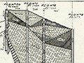
Specifications, Patent No. US647605-A: Expansion-Reamer
Inventor: Charles A. Mentry
Application March 16, 1899 | Granted April 17, 1900
|
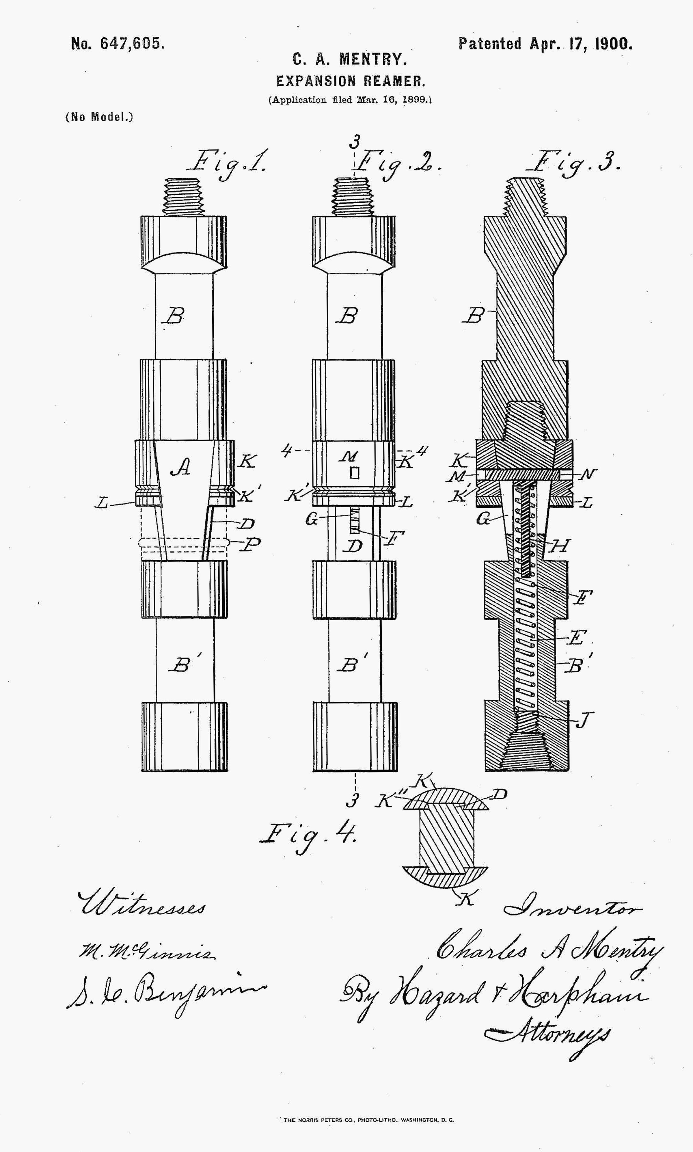
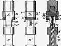
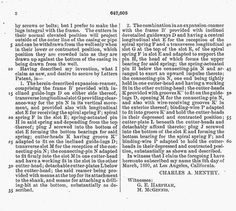
UNITED STATES PATENT OFFICE. CHARLES A. MENTRY, OF NEWHALL, CALIFORNIA. EXPANSION-REAMER. Specification forming part of Letters Patent No. 647,605, dated April 17, 1900. Application filed March 16, 1899. Serial No. 709.351. (No model.) To all whom, it may concern. Be it known that I, CHARLES A. MENTRY, a citizen of the United States, residing at Newhall, in the county of Los Angeles, State of California, have invented a new and useful Expansion-Reamer, of which the following is a specification. My invention relates to improvements in reamers for enlarging a well-hole; and the objects of my improvement are, first, to provide a reamer that will enlarge the well-hole below the casing when necessary, and, second, to provide a reamer which will straighten the hole in case the drill gets the hole out of perpendicular. I attain these objects by the mechanism described herein and illustrated in the accompanying drawings, in which— Figures l and 2 are side views of my reamer and the shank thereof, the plane of one view being at right angles to that of the other. Fig. 3 is a central longitudinal section taken on line 3 3 of Fig. 2. Fig. 4 is a cross-section taken on line 4 4 of Fig. 2. A is the reamer, and B is the shank thereof. They are preferably square in their centers, affording bearings for holding a wrench when being screwed together or taken apart. The frame B' of the reamer is provided with two inclined guide-lugs D, located on opposite sides thereof. These lugs are adapted to fit into the dovetailed grooves K" in the cutter-head K. In the reamer-frame B' is a central cylindrical opening E for the reception of the spiral spring F. This opening extends from the bottom of the reamer to the slot M at the top thereof. It forms a housing for the spiral spring F. Dropping into this spring, at the top end thereof, is the spring-actuated pin H, the head of which rests on the upper end of the spring and forms a bearing for the upper end of the spring. This pin will keep the spring in proper alinement [sic] and prevent it from collapsing when depressed. The head of this pin will at all times be spring-pressed against the square pin N, keeping it in its normal or elevated position. This pin N forms a connection between the cutters K, mounted on either side of the reamer, into one of which the pin is tightly driven and rigidly held, and in the other it has a working fit. This will permit the two halves of the cutter-head on opposite sides of the frame to approach and recede one from the other as they move up or down in the inclined guideways. This pin passes through the transverse longitudinal slot G and has a vertical movement therein. J is a screw-threaded plug screwed into the bottom of the opening E and forms the bottom bearing for spiral spring F. K are semicircular-cutter-heads located one on each side of the reamer-frame and provided with dovetail grooves K" to receive the dovetail guide-lugs D, on which they have a vertical movement. These cutter-heads are provided with cutting-plates L, lying beneath the cutter-heads and detachably affixed thereto in any suitable manner. The cutter-heads are preferably made of iron and the cutter-plates of steel, so that the cutter-plates can be taken off, tempered and sharpened, or renewed, as the wear comes principally on the bottom. Instead of the two cutter-heads one may be used, in which case the inclined guide-lug (upon which it works vertically) should be made larger and stronger. The cutter-head has formed in its outer side a groove K' to receive a wire or cord P (shown in dotted lines in Fig. 1) to bind and hold the cutters in their lowest and contracted position, which position they must be in when the reamer is being lowered through the pipe into the hole. This wire will be broken as soon as the bit strikes the bottom or when the cutter strikes any obstacle in the well, releasing the cutter-head and permitting the spring F to force the cutters upward into their elevated and expanded position, as shown in full lines in the drawings, its depressed or contracted position while tied being shown in dotted lines in Fig. 1. It will be observed that the extent to which the reamer will enlarge a hole depends on the distance one from the other of the inclined guide-lugs D at the upper end thereof. The distance of said lugs one from the other at their extreme lower end should be such that when the cutters are at their lowest position there is a clearance-room in the pipe between the outside of the cutter-head and the inner wall of the pipe for the passage therethrough of the cutter-head. The lugs could be made separate from the frame and fastened thereto by screws or bolts; but I prefer to make the lugs integral with the frame. The cutters in their normal elevated position will project outside of the outer line of the casing or pipe and can be withdrawn from the well only when in their lower or contracted position, which position they are crowded into as they are drawn up against the bottom of the casing in being drawn from the well. Having described my invention, what I claim as new, and desire to secure by Letters Patent, is— 1. The herein-described expansion-reamer, comprising the frame B' provided with inclined guide-lugs D on either side thereof, transverse longitudinal slot G providing clearance-way for the pin N in its vertical movement, and provided also with longitudinal slot E for receiving the spiral spring F; spiral spring F in the slot E; spring-actuated pin H in said spring and depending from the top thereof; plug J screwed into the bottom of slot E forming the bottom bearings for said spring; cutter-heads K having groove K" adapted to fit on the inclined guide-lugs D; transverse slot M for the reception of the connecting-pin N; the connecting-pin N adapted to fit firmly into the slot M in one cutter-head and have a working fit in the slot in the other cutter-head; detachable cutter-plates L below the cutter-head; the said reamer being provided with means at the top for its attachment to the shank, and means for attaching a drilling-bit at the bottom, substantially as described. 2. The combination in an expansion-reamer with the frame B' provided with inclined dovetailed guideways D and having a central longitudinal slot E for the reception of the spiral spring F and a transverse longitudinal slot G at the top of the slot E, of the spiral spring F in slot E and adapted to support the pin H, the head of which forms the upper bearing for said spring; the spring-actuated pin H below the connecting-pin N and arranged to exert an upward impulse thereto; the connecting-pin N, one end being tightly held in one cutter-head and having a working fit in the other cutting-head; the cutter-heads K provided with grooves K" to fit on the guide-lugs D, opening M for the connecting-pin N, and also with wire-receiving grooves K' in the exterior thereof; binding-wire P adapted to fit into groove K' and hold the cutter-heads in their depressed and contracted position; cutter-plate L beneath the cutter-heads and detachably affixed thereto; plug J screwed into the bottom of the slot E and forming the bottom bearing for the spiral spring F; and binding-wire P adapted to hold the cutter-heads in their depressed and contracted position, substantially as shown and described. In witness that I claim the foregoing I have hereunto subscribed my name this 8th day of March, 1899, at Los Angeles, California. CHARLES A. MENTRY.
Witnesses: (By Hazard & Harpham, Attorneys)
Original printed version of this text: | Specifications Page 1 | Specifications Page 2 | (Courtesy of Donna Roth Phipps)
|
CSOW Time Book
1887-1889
CSOW Stock Certificate 1901
SCV History Moment
Early Oil & Gas Production in Calif. (Video 1985)
Standard Oil Co. History to 1929
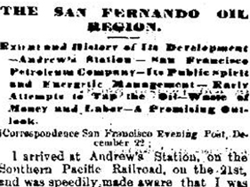
Description Jan. 1877
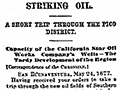
Description May 1877
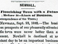
Description 9-26-1882
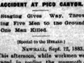
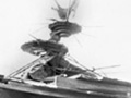
Oil Tank Const. & Death 1883
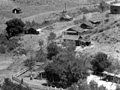
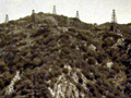
Mentryville 1885-1891
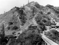
CSO Hill 1883
Oil Works ~1885
The Pico Field 1890
PCO Hill ~1890s
CSO Jackline Plant
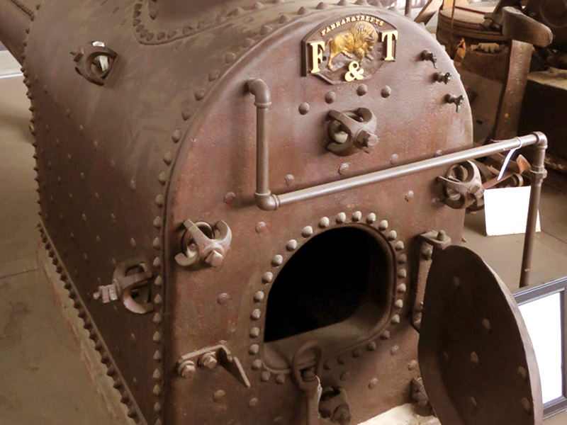
Farrar & Trefts Boiler
New Boiler 1893?
Mentryville 1890s-1900s
Reamer Patent 1900
Machine Shop 1910
Machine Shop 1910s
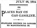
Natural Gas-to-Gasoline 1913/14
Mentryville ~1920
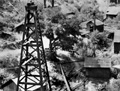
Pico No. 4, 1931
CSO Jackline Plant
PCO Jackline Plant Remnants
Darryl Manzer at Firehouse ~1961
Darryl Manzer at Field Office ~1961
Pico No. 4, 1961
Darryl Manzer, L.A. Times Story 1962
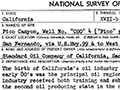
National Survey 1963
PCO Jackline Plant Removal 1974-75
CSO Jackline Plant 1974-75
A.C. Mentry Blacksmith Forge
|
The site owner makes no assertions as to ownership of any original copyrights to digitized images. However, these images are intended for Personal or Research use only. Any other kind of use, including but not limited to commercial or scholarly publication in any medium or format, public exhibition, or use online or in a web site, may be subject to additional restrictions including but not limited to the copyrights held by parties other than the site owner. USERS ARE SOLELY RESPONSIBLE for determining the existence of such rights and for obtaining any permissions and/or paying associated fees necessary for the proposed use.
